Ceramic Capacitor Self Heating

Applied Voltage And Self Heating Temperature Design Safety Application Guide For Multilayer Ceramic Chip Capacitors Electronic Components Devices Kyocera

2019 Hot Sale Holland Bc 20pcs 50pcs 100v 150pf N15 150p High Frequency Silver Film Ceramic Capacitor Free Shipping Capacitors Led Sign Board Led Video Wall

Capacitor Types Of Capacitors Fixed Variable Polar Non Polar Capacitors Diy Electrical Electrolytic Capacitor

Where Did The 0 1 Uf Value For Bypass Capacitors Come From Capacitors Bypass Hobby Electronics

Series Capacitor Features High Self Resonance Flash Drive Usb Flash Drive

Types Of Capacitors Electrolytic Variable Film Capacitors Capacitors Electrical Projects Electrolytic Capacitor

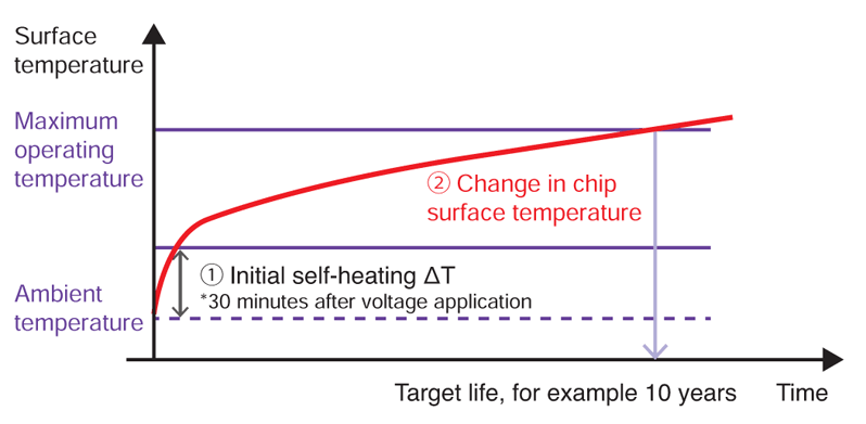
The load should be contained so that the self heating of the capacitor body remains below 20 c when measuring at an ambient temperature of 25 c.
Ceramic capacitor self heating.

Capacitor Ceramics An Overview Sciencedirect Topics

Product Information Film Capacitor Technical Notes Hybrid Capacitor Power Supply Units Rubycon Corporation

Pin On 3d Printer Parts Accessories

Ac Motor Capacitor Capacitors Electronic Products Earbuds

Product Information Pmlcap Technical Notes Hybrid Capacitor Power Supply Units Rubycon Corporation

Faq Capacitors Faq Electronic Components Devices Kyocera

Diy Induction Heater Induction Heating Induction Heater

Wet Tantalum Capacitor Meets Mil Prf 39006 33 Specs Capacitors Wet Specs

Mallory 150m Axial Coupling Capacitor 0 0047uf 630v By Mallory Capacitors 0 64 High Quality Mallory 150 Electronics Components Capacitors Car Electronics
2015 New Arrival 2pcs Elna For Ina S Top For Audio Stereo Filtering 10000uf 63v 30 50mm Electrolytic Capacitors Free Electrolytic Capacitor Capacitors Stereo

Resistor Helper Is An Alexa Skill That Will Give You The Resistor Value For Any Given Four Band Sequence Which Really Comes Resistors Circuit Components Hs10
Resonant Mlcc For High Power Wireless Charging Murata Manufacturing Articles

How To Make 7000f Ultra Capacitor Diy Homemade Super Capacitor From Aluminum Foil Youtube Capacitors Electronics Projects Nordstrom Kids


Capacitors Selection Guide Tech Notes Capacitors Tdk Product Center

Pin On Office Accessories

Hybrid Polymer Capacitors Boost Endurance With Low Leakage Current Capacitors Electrolytic Capacitor Current

Microwaves101 Self Resonant Frequency

Vintage 1963 Electronics Radio Capacitors Parts Print Advertising Ad Original Print Advertising Capacitors Advertising Ads

Thyristor Silicon Controlled Rectifier Scr Thyristors Applications Electronic Engineering Electronic Parts Control

Ntc Thermistor 10k Resistors 10k Electronics

Ebay Sponsored Siemens Qj23b12500s01 Molded Case Circuit Breaker Bolt On 240v 125 Amp In 2020 Glass Ceramic Breakers Siemens

Pin On Capacitors

Wet Tantalum Capacitor Offers Established Reliability Radio Electronics Com Capacitors Wet Offer
Source : pinterest.com
